Matrix hexpansion lite loop kit
Build your own Matrix Hexpansion with this part-assembled kit for a 156-LED monochrome matrix.
Contents
- 1× matrix hexpansion base board (
v2, populated with CH32V006 processor) - 1× LED daughter board (
lite-loop, unpopulated) - 13× 91 Ohm 0603 resistors (on a 6 cm paper strip with cover tape, with a few spares)
- 156× green or white 0603 LEDs (on a 64cm plastic strip with cover tape, cut from a reel, with a few spares)
You will need
- Soldering iron with medium or fine tip
- Fine solder wire
- Soldering flux
- Tweezers
- Optional: hot plate or hot air station, solder paste syringe
- Optional: some magnification, something to hold the board in place while soldering
A fine-tipped soldering iron may be needed to connect the base and LED boards together. It may be easier to solder the LEDs with a hot plate or hot air tool, but it can also be done with just a soldering iron and fine solder wire.
Assembly
Initially orient the board so the straight side is facing up, and the curved side is facing down.
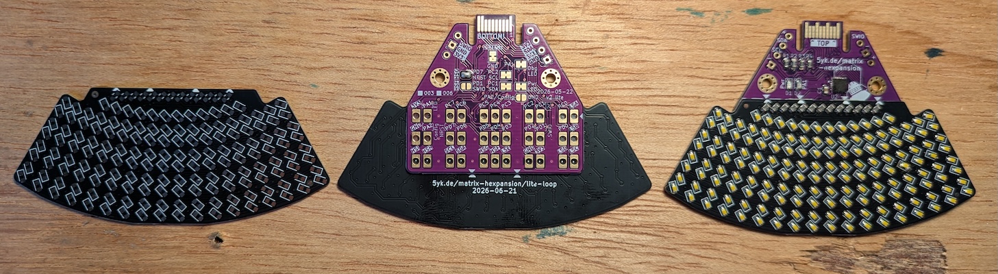
1. Resistors
The top row of slightly smaller 45° angled pads is for the 13 resistors.
2. LEDs
The LEDs are marked on the top with a tiny green dot on the cathode (pin 1, negative) side. This must be aligned with the marked side (the horizontal bar on the U-shaped marking around one of the pads) on the board silkscreen. On this board, the rows alternate between cathode-up (left) and cathode down (right).
On this board all LEDs should be the same type and colour, or the matrix multiplexing may break down.
3. Base
In these kits, the base board should already be populated with four resistors, two LEDs, a capacitor, and the CH32V006 processor.
Flip the lite-loop board over and apply some flux to the large exposed pads.
Place the base board, bottom side up, on the pads. Use the arrows and the center dots in the bottom row of pads to align.
Use the fine-tipped soldering iron to heat up the matching pads on both boards, then add a little bit of solder to make the connection. Starting from the center, repeat this for all the large pads.
4. Testing
Plug the hexpansion into your badge, and you should see the default Starfield pattern.
Open the Matrix Hexpansion app (Apps category, code 41214133)
Using the app, set “all to constant” (255, 100%). It is quite likely that not all LEDs will light up the first time you connect the board.
The “fill” pattern may also be useful to identify if any LEDs are in the wrong orientation.
Common problems:
- Individual LEDs not lighting up: check the solder joints of the LED. Tap them with a soldering iron while powered and you may see the LED flicker. Apply some more flux and solder to correct.
- LEDs lighting up in the wrong order: double check the polarity of the LED. Desolder the LED with some more flux and solder to correct.
- Connected patterns of LEDs not lighting up: check the resistor solder joints, and check the pads connecting to the base. You may need to consult the KiCad project to identify which base pad is responsible for the affected column (select a pad, and highlight the net to find the resistor and base pad responsible for that column). While the board is powered, push the fine tipped soldering iron into the corresponding pad and check if the LEDs now come on. If you’ve identified the right pad, apply some more solder until a reliable connection is made. If this still doesn’t resolve it, there may be a bad solder joint on the processor itself. Add some flux and carefully pull a clean fine tipped soldering iron along the edges of the processor.